Linear: A Rapid Prototyping Project
Project Background
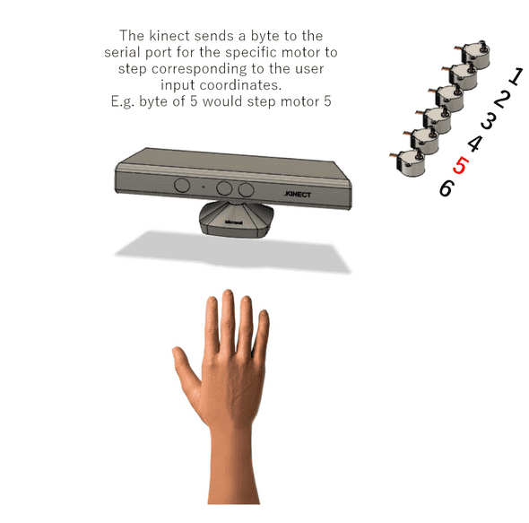
Our goal was to create an intuitive interface that allows the user to make gestures to manipulate their physical environment. More specifically, the user controls the display through hand gestures under an XBox Kinect sensor. The image of the Kinect is read in real-time and translated into x-y and depth values, which are then sent to the Arduino and translated into a form that indicates which motors should run, which direction they should rotate in, and the number of steps they should run for. The motor functions are regulated by the Arduino/C++ code.
Outcome
While this project was intended to be just an initial prototype, the final product we created was able to achieve the design goals we had envisioned. In addition, this interface invokes further research and design in two domains: first, it allows users to manipulate a 3D surface remotely, encouraging the development of devices to precisely mirror gestures in applications such as remote teaching or accessibility services. Next, it raises the possibility of interacting with our world in a 3D manner rather than the 2D manner that prevails in our phone and computer screens.
Functional Units
There are two main functional units to the project: the block display and the user control area. The user interaction aspect is executed with a Kinect, where the Kinect is able to detect the user’s hand motions in a 3D plane. The boundaries of the Kinect’s sensor determine how the area in between is split into thirty squares in the x-y coordinate plane. Each of these squares corresponds to a block in the block display. The depth of the user’s hand in relation to the Kinect determines the height of the block when it rises in the block display. The functional unit of the box display is comprised of stepper-powered pin movement, where the timing and amount of stepper rotation is controlled from the translated data being received from the Kinect.
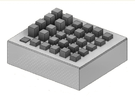 Box & Grid design created with Fusion 360
The block display integrates several essential components. Visible from the outside are the 30 blocks distributed across a chipboard grid with slots measured to fit each block precisely. Each block is spaced 2 cm apart from each other on every side. At rest, the boxes stick just 1 cm above the surface of the grid, with the other 14 cm of the block length housed inside the box for a total height of 15 cm. As shown in the figure above, each of these blocks is hollow to accommodate its internal components.
The Kinect is mounted on a stand close to the block display. The user’s gestures below the Kinect which registers the 3D coordinates. The reading from the Kinect is stored and manipulated to control the movement of the blocks in the block display. That is, the field in the Kinect camera is mapped to the 30 blocks, and the depth sensor determines the range of motion by the block.
Design Process
Paper Sketches
The early stages of the project began with brainstorming sessions about required materials and design proposals. To flesh out early ideas, we began with sketching different versions of the system (box grid and user control area).
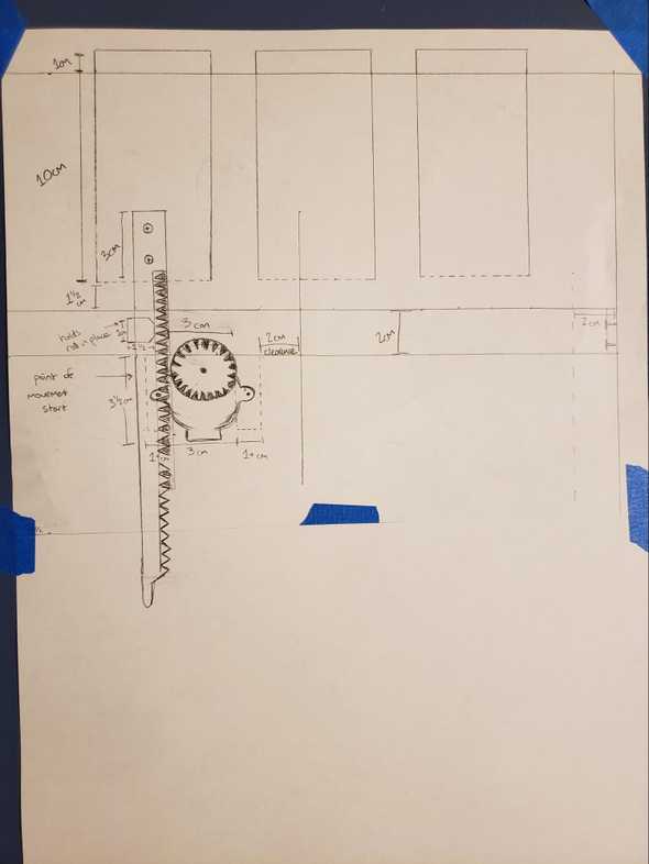 Sketch of rack and motor mechanism
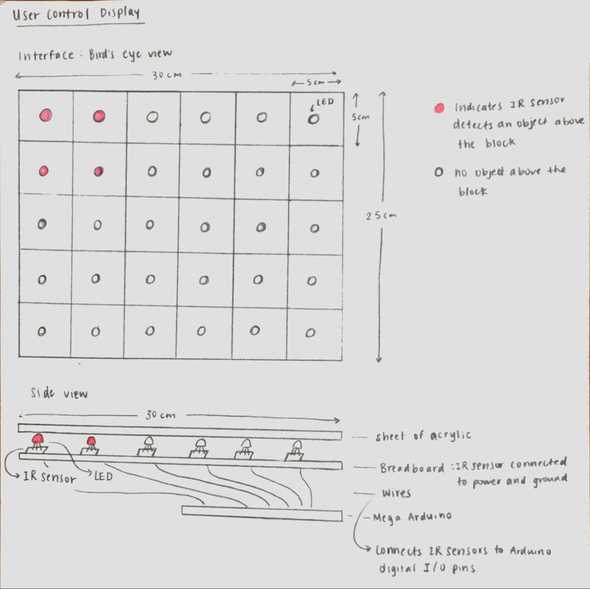
Noteably, initial sketches of the user control area did not include a Kinect at all. Instead, we determined having 30 IR sensors to map to the 30 blocks on the box display would be an intuitive design.
Cardboard Prototype
After sketching initial designs, we started working on a cardboard and leggo prototype, The rationale behind this is that we would be able to validate some of our assumptions about the integrity of our design structures without incurring excessive costs.
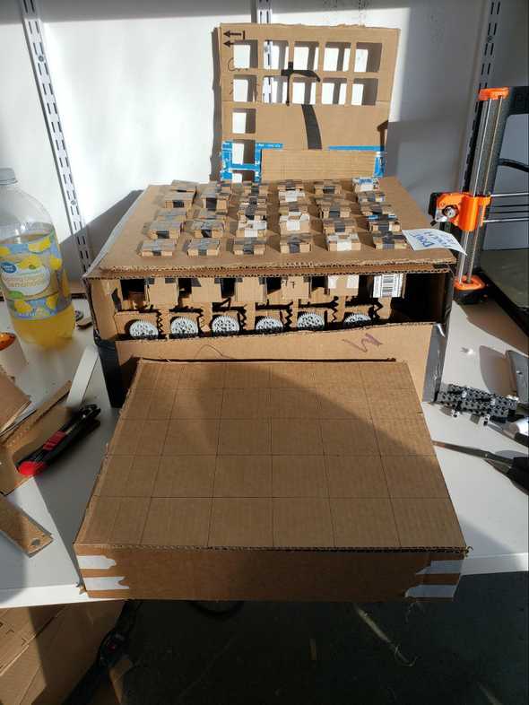 Cardboard prototype of box grid and IR control area
We originally intended for the grid to consist of squares of 4 cm * 4 cm to match the size of the blocks, but realized through our cardboard prototype that the user’s hand would take up too much space with respect to the entire control board, thereby moving more blocks in one motion than intended. This discovery justifies our use of cardboard prototyping, avoiding what could have been a costly mistake when purchasing and cutting more expensive materials.
Partial Prototype
After making adjustments from the cardboard prototype, we decided to test a singular row of boxes to test our new design.
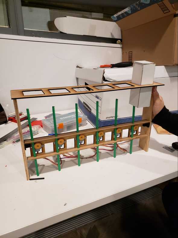 Partial prototype testing 6 boxes
As expected, we discovered new issues that we would repair in later interations - mainly, the teeth on our racks and pinions were way too small and prone to slippage.
This stage of the design included laser cutting clipboard sheets for the boxes, and wood for the supporting structures. It also included 3D-printing the racks and pinions.
Design Challenges
The system uses the rack and pinion mechanism to convert the rotational movement of the motors into linear movement.
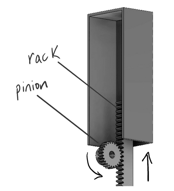 Rack & pinion demonstrated using Fusion 360
Our initial Fusion 360 model of the rack and pinion had small teeth which an earlier iteration revealed would cause slippage. In the final prototype we made the teeth bigger which was much more effective in guaranteeing consistent locking between rack and pinion.
Additionally, the motors are powered by two 5V power supplies. After experiencing issues with motors drawing too much current, we eventually determined, with the guidance of Professor Guimbretière, that having two 5V 2A power supply to provide voltage to 15 motors each would be sufficient as opposed to our plan of using 5V voltage regulators. The power supplies were able to move the motors as expected.
Also, in an earlier iteration of the prototype we intended on using 30 IR sensors to map the gestures to block movements. Below is a simplified circuit model depicting how a particular IR sensor would have mapped to a stepper motor.
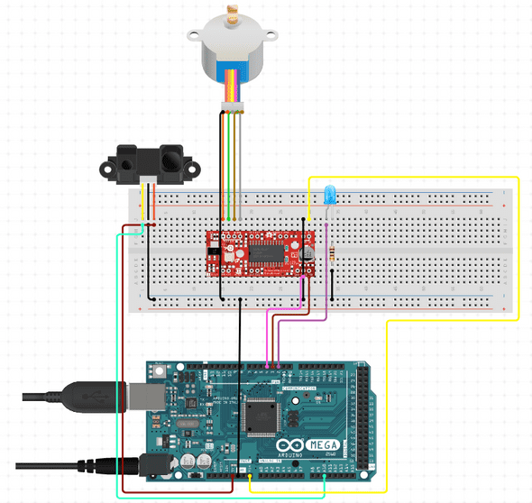 Simplified circuit diagram showing the relationship between IR input and motor output.
In light of intermediary iterations, we realized that using 30 IR sensors posed two major issues:
- 30 IR sensors would require scores of wires crammed into a small space. This would likely become very unmanageable and significantly increase wiring errors.
- Working with a limited budget, we would likely not have the resources to sufficiently spread the IR sensors out enough to yield accurate mappings.
With the advice of Professor Guimbretière, we decided that using the Kinect for gesture detection would be more time efficient and easier to manage.
Future Work
There were a few potential areas for improvement discovered after demonstrating our final prototype. Although our physical assembly functioned well enough to create the desired effect, we could have produced more impressive results had the pins moved faster in response to user input. In our final prototype the stepper movement was gradual and so users often had a hard time seeing how precisely the mapping of their movements was occurring since they would have to hold their hand in place long enough for the pins to move into place. Faster stepper motor movement could have been achieved by increasing the current limit or supplied voltage, but we hesitated to damage our motors in the process of experimentation with increasing the speed. Additionally, the assembly occasionally had some random blocks moving based on ghost inputs on the Kinect camera, but this problem is something we would likely not be able to solve with our assembly or integration.
For a more detailed report on this project, click here.
